Defeaturing Concepts#
Understand the fundamentals of shape editing before using the API.
Note
Start here if you’re new to defeaturing. This section explains the motivation, terminology, and core concepts you’ll need to use the shape_editing module effectively.
Shape Editing: Defeaturing CAD Models#
Shape editing in volmdlr_tools refers to modifying CAD models by removing geometric features while maintaining a valid solid. This process is commonly known as defeaturing.
Why Defeature?#
Defeaturing is essential in several CAD workflows:
Simplification for Simulation Finite Element Analysis (FEA) and Computational Fluid Dynamics (CFD) software generate meshes from CAD geometry. Small features like fillets and chamfers create dense mesh regions that increase computation time without significantly improving accuracy. Removing these features produces simpler meshes that solve faster.
Manufacturing Analysis Manufacturing engineers often need to identify the “core” geometry of a part, separate from finishing features. By removing blends and fillets, you can analyze the fundamental shape and its manufacturability.
Model Comparison When comparing design iterations, small differences in fillets or chamfers can obscure significant geometric changes. Defeatured models reveal the essential structural differences between designs.
File Size Reduction Complex features increase the number of faces in a BRep model. Simpler geometry means smaller files and faster loading times.
What is Defeaturing?#
Defeaturing is the process of removing geometric features (fillets, chamfers, holes, pockets) from a BRep model while maintaining topological validity.
BRep Basics#
Before diving into defeaturing, let’s review the key components of a BRep (Boundary Representation) model:
Face: A bounded portion of a surface. Each face has a surface type (plane, cylinder, cone, sphere, torus, or freeform).
Edge: A bounded curve where two faces meet.
Vertex: A point where edges meet.
Wire: A connected sequence of edges forming a closed or open loop.
A valid solid must be “watertight” - every edge must be shared by exactly two faces, and all faces must form a closed boundary.
The Challenge#
Defeaturing is not simply deleting faces. When you remove a face:
Neighboring faces have gaps - The surrounding faces must extend to fill the space left by the removed face.
New edges form - Where the extended faces meet, new edges are created.
Topology changes - The face adjacency relationships are modified.
If the surrounding surfaces cannot extend cleanly (for example, they intersect in complex ways), the defeaturing operation fails.
Core Concepts#
Soft vs Hard Features#
volmdlr_tools classifies features into two categories based on how difficult they are to remove. The following example demonstrates both types on the same part:
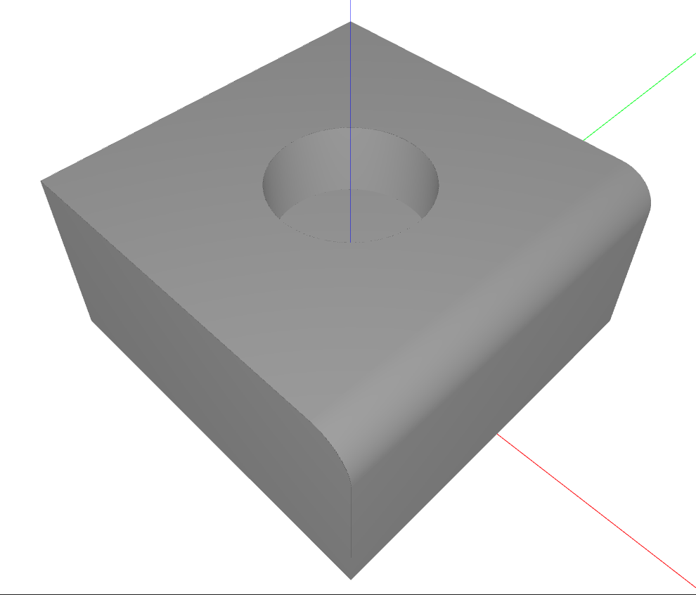
Soft (Isolated) Features
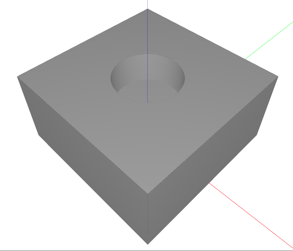
A soft feature is one where the feature faces are completely “inside” a hole or opening in the neighboring faces. Think of a cylindrical hole in a flat plate - the hole’s cylindrical face is bounded by an inner wire of the plate’s flat face.
Characteristics of soft features:
All common edges with neighboring faces lie on inner wires (holes/openings)
Can be removed by simple face deletion
The surrounding faces naturally close the gap
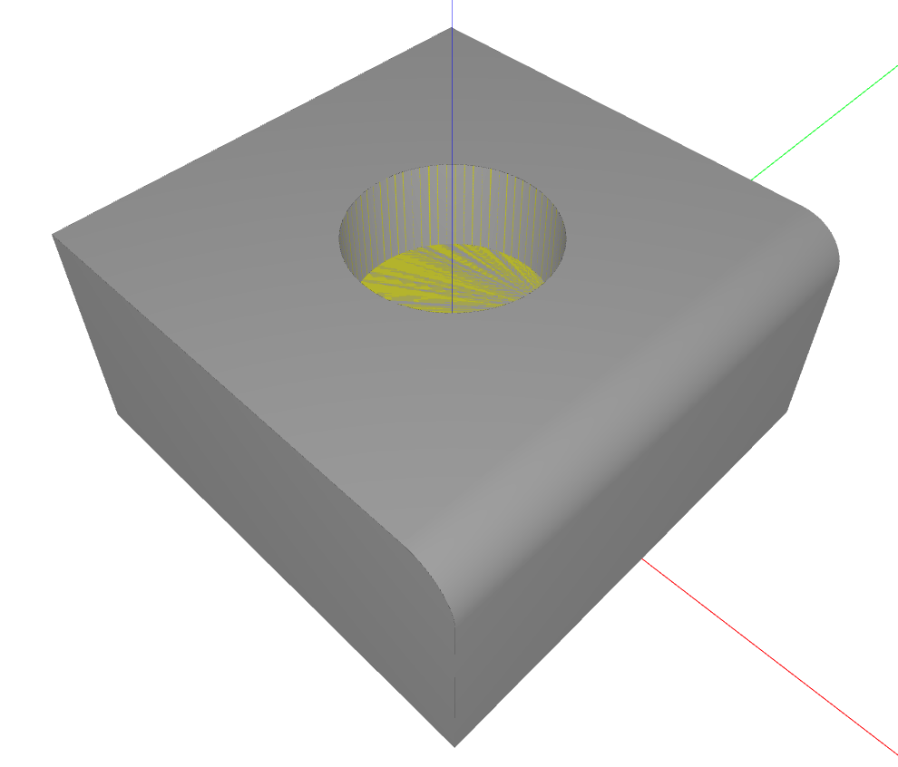
In the image below, the hole is highlighted in yellow. It’s a soft feature because its edges lie entirely on the inner wire (hole boundary) of the top face:
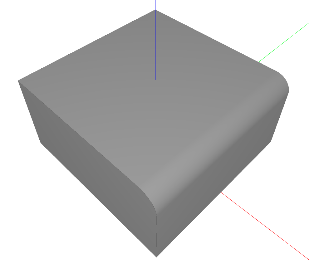
After removal, the top face simply closes over the hole:
Hard (Complex) Features
A hard feature shares edges with the outer boundary of neighboring faces. A fillet at the edge of a block is a classic example - the fillet face shares edges with the outer boundaries of two perpendicular faces.
Characteristics of hard features:
Common edges touch the outer wire (boundary) of neighboring faces
Require advanced algorithms to remove
Surrounding surfaces must be extended and intersected
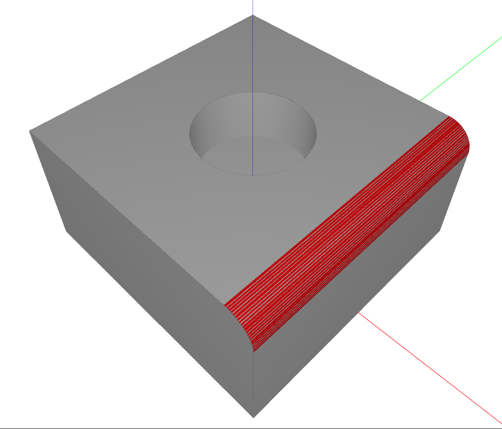
In the image below, the fillet is highlighted in red. It’s a hard feature because its edges are part of the outer boundary of the adjacent faces:
After removal, the neighboring faces are extended and intersected to create sharp edges:
The Two-Stage Strategy#
volmdlr_tools uses an intelligent two-stage approach:
Try soft removal first: Attempt to remove the feature using simple face deletion. This is fast and reliable when applicable.
Fall back to hard removal: If soft removal fails (because the feature is hard), an advanced defeaturing algorithm is used. It extends the surrounding surfaces, computes their intersections, and rebuilds the topology to fill the gaps left by the removed feature. This approach handles most cases, but may fail for complex geometries involving non-planar surfaces or many intersecting faces.
This strategy optimizes for both speed (soft removal is faster) and robustness (hard removal handles complex cases).
History Tracking#
When you perform multiple defeaturing operations in sequence, you often need to know:
What happened to a specific face?
Was it deleted, or did it become a different face?
Can I trace the evolution of the original geometry?
volmdlr_tools provides the HistoryGraph class to answer these questions. It maintains a directed acyclic graph (DAG) tracking how shapes evolve through operations. This is covered in detail in the History Tracking section.
Prerequisites#
Before using the shape_editing module, you should be familiar with:
Basic CAD terminology (faces, edges, BRep)
volmdlr.shapes.Solidandvolmdlr.shapes.Shellclasses(Optional)
AttributedAdjacencyGraphfor advanced use cases
Next Steps#
Defeaturer Tutorial: Learn to use the high-level API
History Tracking: Understand shape evolution tracking
See Also#
Defeaturer - Main high-level API tutorial
History Tracking - Shape evolution tracking
Attributed Adjacency Graph (AAG) - Attributed Adjacency Graph (used internally)