

Section on how to create Complex volmdlr objects#
Volmdlr now uses the Boundary Representation Theory (BRep), where to construct valid solids, the following extended version of the Euler–Poincaré formula shall be satisfied:
where V, E, F, L and S are the numbers of unique vertices, edges, faces, face bounds and shells in the model and G is the sum of the genus of the shells
Let’s clarify this formula and its consequences with an example (let’s consider the reduced version of the formula for simplicity, V−E+F=2):
Suppose we have a cube as in the image below.
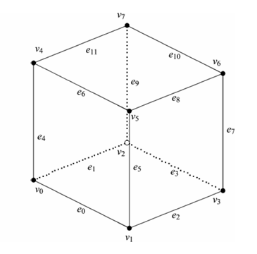
A cube has:
8 vertices (V);
12 edges (E);
6 faces (F);
Plug these values into the Euler-Poincaré formula:
This cube adheres to the Euler formula and is considered a manifold solid.
Now, let’s consider an alternative method for constructing the same solid: by first constructing each face individually and then assembling these faces into a list to instantiate a shell. Each planar face has 4 vertices and 4 edges instances. In this case, we would have:
24 Vertices (V);
24 Edges (E);
6 Faces (F);
Applying the Euler formula to this scenario, we get:
As we can see, the result is different from 2, indicating that simply grouping faces without adhering to certain rules does not guarantee a valid solid. Some rules must be followed, such as ensuring that connected edges share the same vertices and that adjacent faces share the same edges.
To more detail about manifold solid, please visit: https://www.steptools.com/stds/smrl/data/resource_docs/geometric_and_topological_representation/sys/6_schema.htm#geometric_model_schema.manifold_solid_brep
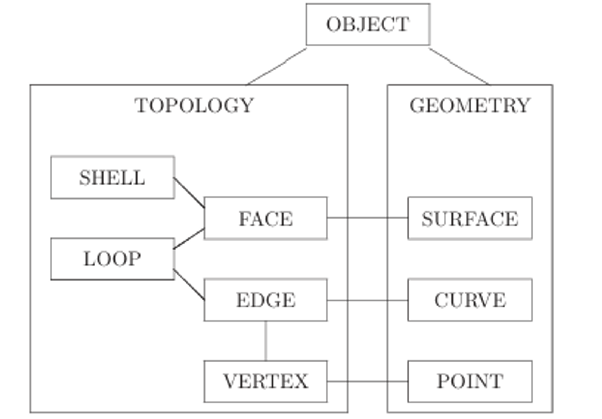
Brep, in resume immerses Geometry into Topology.
Geometry: defines the shapes of objects;
Topology: defines the connectivity of shapes;
A face lies on a surface, an edge lies on a curve, and a vertex lies on a point. Surfaces, curves, and points have geometric definitions that dictate how they are parametrically defined in space, thereby shaping objects.
On the other side, faces, edges, and vertices are topological entities. They not only receive geometric inputs but also define the structure and connectivity of shapes. In the accompanying image, we can interpret the term “OBJECT” as representative of our Solid, while “LOOP” symbolises our wire objects.
Shapes: Shell, Solid, Compound#
Because now to have connected edges in a wire they must share the same vertices, and adjacent faces in a shell must share the same edges, the recommended way to create shells with faces has changed, and now there will be some class methods which will do all the work of verifying these rules to ensure a final manifold object.
Now, with the introduction of a Solid - which is defined as 3D object that follows Brep rules presented, and contrary from a shell that represent a surface or a thin, hollow structure lacking mass and volume, a solid has mass and volume and it has a well-defined interior bounded by surfaces - there may be the concept of outer shells and inner shells of a solid, where the faces of the outer shell and inner shells should also be pointing to the exterior of the volume.
Moving forward, while existing classes will largely retain their functionalities and instantiation processes, the introduction of a new module, shapes.py, will replace the deprecated shells.py. This new module will feature classes such as Shell, Solid, and Compound:
Shell: Represents a shell comprising a list of faces assembled to form a hollow structure.
Solid: Similar to a shell, but forming a solid with mass and volume, without hollowness.
Compound: A container for multiple Solid and Shell objects.
While it remains possible to define a shell and consequentlly solids from a list of faces, it’s important to note that this approach is not recommended. It becomes increasingly challenging to adhere to all the necessary rules, especially when constructing complex solids.
Therefore, as previously mentioned, class methods are now provided to assist in creating shells and solids while ensuring compliance with these rules. This eliminates the need for users to remember every rule and it’s much easier and intuitive then constructing all the faces one by one with code. Below are some basic examples of each method.
Elementary Primitives#
Elementary shapes are basic geometrical shapes that can be used as building block to accelerate the design process. Below are usage examples on how to use these features.
shapes.Solid.make_box
from volmdlr import shapes
import volmdlr

box = shapes.Solid.make_box(length=2, width=3, height=5, frame=volmdlr.OXYZ)
box.color=(0.3, 0.5, 1)
box.display_3d()
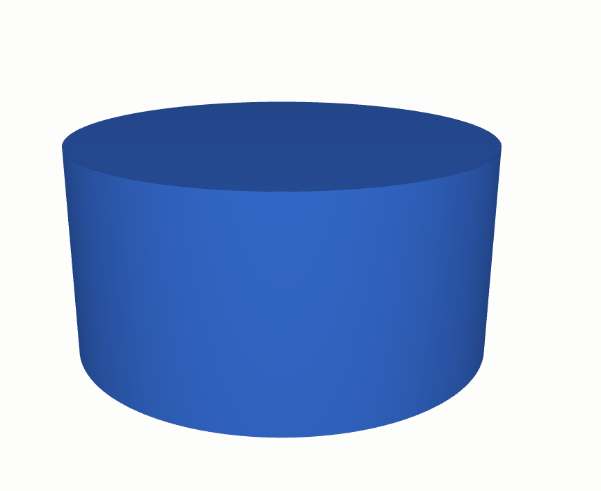
shapes.Solid.make_cylinder
from volmdlr import shapes
import volmdlr

cylinder = shapes.Solid.make_cylinder(radius=5, height=5, frame=volmdlr.OXYZ)
cylinder.color=(0.3, 0.5, 1)
cylinder.display_3d()
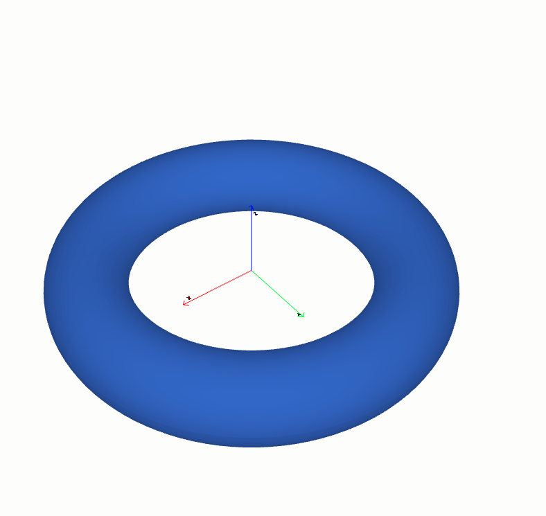
shapes.Solid.make_torus
from volmdlr import shapes
import volmdlr

torus1 = shapes.Solid.make_torus(radius1=2, radius2=.5, frame=volmdlr.OXYZ)
torus1.color=(0.3, 0.5, 1)
torus1.display_3d()
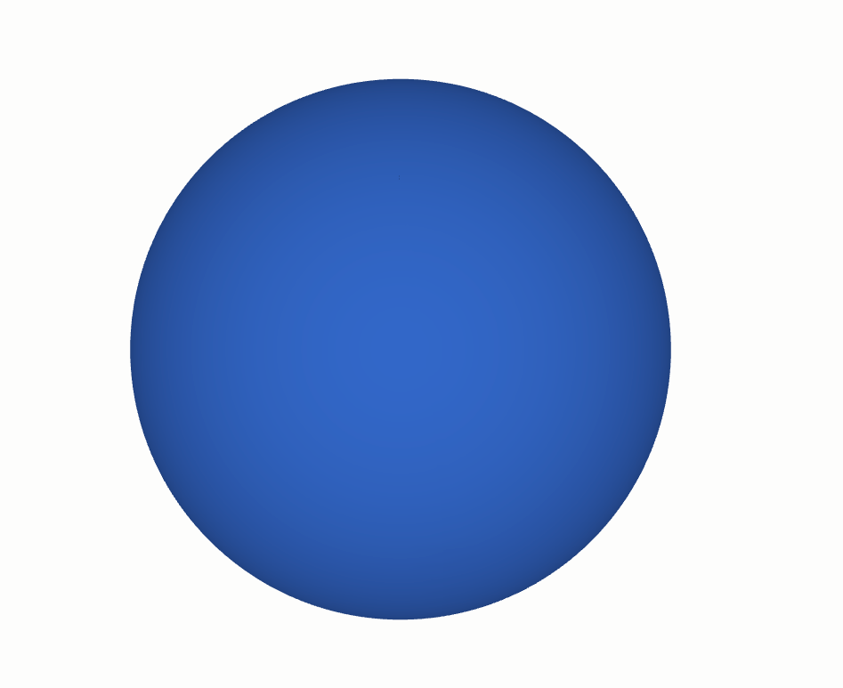
shapes.Solid.make_sphere
from volmdlr import shapes
import volmdlr

sphere1 = shapes.Solid.make_sphere(
    radius=5,
    frame=volmdlr.OXYZ,
    angle1=-math.pi / 2,
    angle2=math.pi / 2,
    angle3=2 * math.pi,
    name='',
)
sphere1.color=(0.3, 0.5, 1)
sphere1.display_3d()
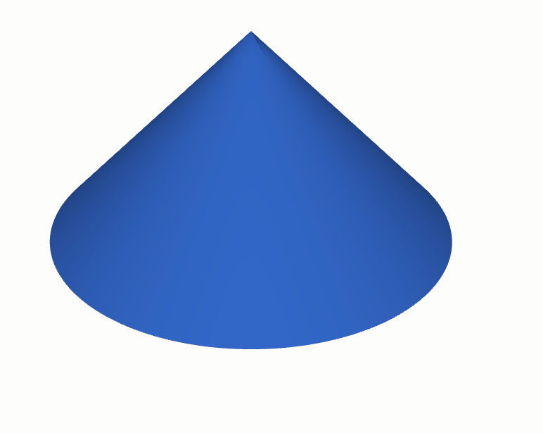
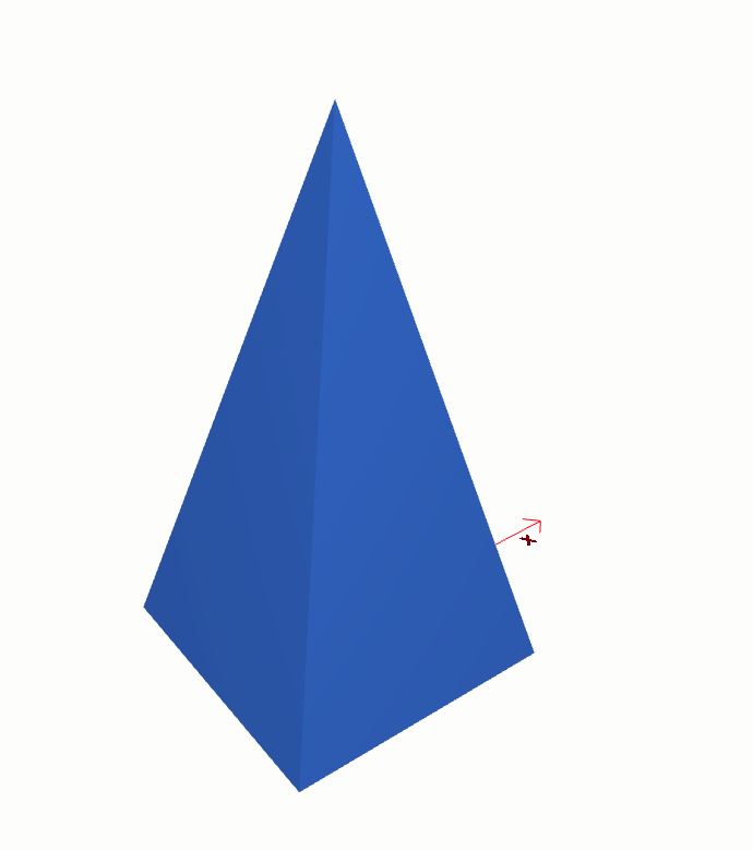
shapes.Solid.make_cone
from volmdlr import shapes
import volmdlr

cone = shapes.Solid.make_cone(radius1=5, radius2=0, height=5, frame=volmdlr.OXYZ)
cone.color = (0.3, 0.5, 1)
cone.display_3d()
shapes.Solid.make_wedge
from volmdlr import shapes
import volmdlr

dx, dy, dz = 1, 2, 1
solid = shapes.Solid.make_wedge(
    dx=dx,
    dy=dy,
    dz=dz,
    xmin=dx / 2,
    xmax=dx / 2,
    zmin=dz / 2,
    zmax=dz / 2,
    local_frame_origin=volmdlr.Point3D(-0.5, 0.5, 0.0),
    local_frame_direction=-volmdlr.Y3D,
    local_frame_x_direction=volmdlr.X3D,
)
solid.color=(0.3, 0.5, 1)
solid.display_3d()
Constructive Primitives#
Constructive primitives have as construction principle sweeping some shape(profile) along a path. The path can be:
Linear
Rotational (through an angle of rotation)
Freeform (sweep along a given path or a loft)
The profile generates objects according to the following rules:
Vertices generate Edges
Edges generate Faces.
Wires generate Shells.
Faces generate Solids.
Shells generate Composite Solids
So, for example, if you want to create a solid with an extrusion, you need to extrude a planar face. However, since we are accustomed to working with wires and frames, we have also provided special class methods, like shapes.Solid.make_extrusion_from_frame_and_wires, that accept these low-level objects. Behind the scenes, this method constructs the necessary face for the extrusion that should be used if you want to directly use shapes.Solid.make_extrusion.
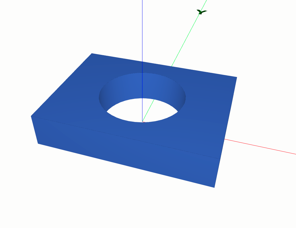
shapes.Solid.make_extrusion
from volmdlr import shapes, wires, curves
import volmdlr

length, width, height, radius = 0.4, 0.3, 0.08, 0.1
outer_contour2d = wires.Contour2D.rectangle_from_center_and_sides(
    volmdlr.O2D, x_length=length, y_length=width, is_trigo=True
)
inner_circle = curves.Circle2D.from_center_and_radius(
    volmdlr.O2D, radius, is_trigo=False
)
inner_contours2d = [wires.Contour2D.from_circle(circle=inner_circle)]
solid = shapes.Solid.make_extrusion_from_frame_and_wires(
    volmdlr.OXYZ, outer_contour2d, inner_contours2d, height
)

solid.color=(0.3, 0.5, 1)
solid.display_3d()
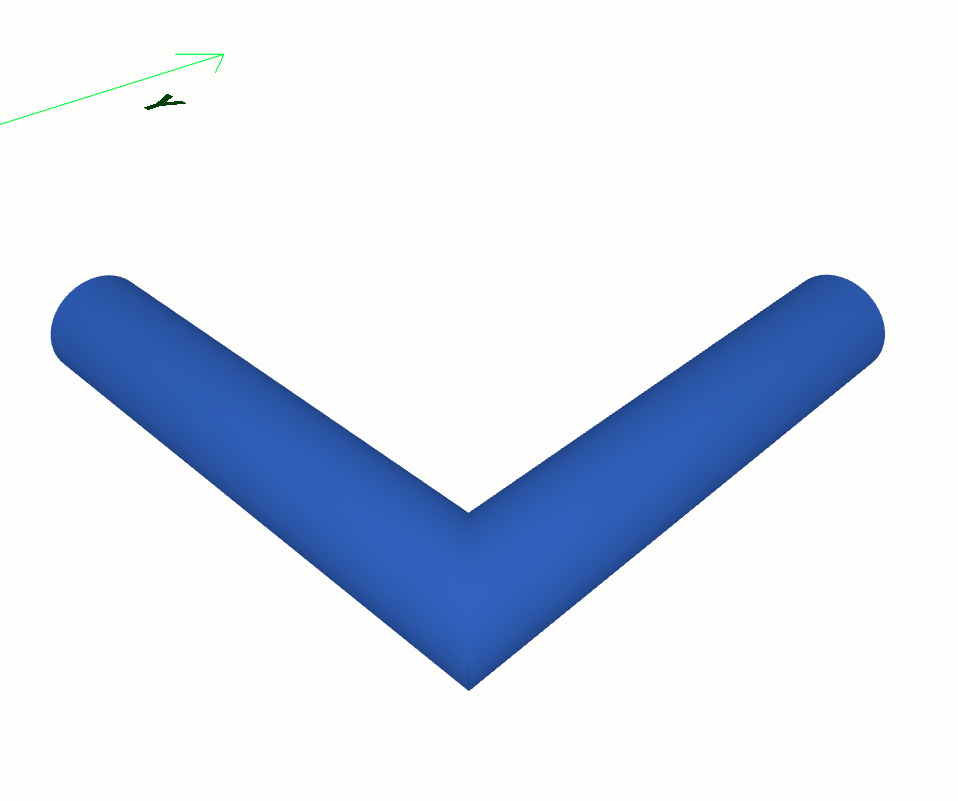
shapes.Solid.make_sweep
from volmdlr import shapes, curves, faces, surfaces, wires
import volmdlr

point1 = volmdlr.Point3D(1.0, 1.0, 0.0)
point2 = volmdlr.Point3D(1.0, 0.5, 0.0)
point3 = volmdlr.Point3D(0.5, 0.5, 0.0)

outer_contour = wires.Contour2D.from_circle(
    curves.Circle2D(volmdlr.OXY, 0.05)
)
inner_contours = [
    wires.Contour2D.from_circle(curves.Circle2D(volmdlr.OXY, 0.045))
]
direction = (point2 - point1).unit_vector()
frame = volmdlr.Frame3D.from_point_and_vector(
    point=point1, vector=direction, main_axis=volmdlr.Z3D
)
section = faces.PlaneFace3D(
    surface3d=surfaces.Plane3D(frame=frame),
    surface2d=surfaces.Surface2D(
        outer_contour=outer_contour, inner_contours=inner_contours
    ),
)

path = wires.Wire3D.from_points([point1, point2, point3])
sweep1 = shapes.Solid.make_sweep(
    face=section, path=path, transition_mode="right"
)
sweep1.color=(0.3, 0.5, 1)
sweep1.display_3d()
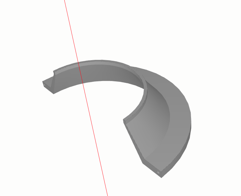
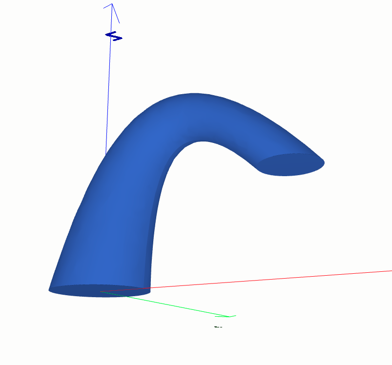
shapes.Solid.make_revolve
from volmdlr import shapes, curves, faces, surfaces, wires
import volmdlr

r = 0.15
R = 0.2
Rb = 0.25
w = 0.2
wb = 0.02
th = 0.008
rim_contour = wires.Contour2D.from_points([
    volmdlr.Point2D(-0.5 * w, Rb),
    volmdlr.Point2D(-0.5 * w + wb, Rb),
    volmdlr.Point2D(-0.5 * w + wb, R),
    volmdlr.Point2D(-0.05 * w, r),
    volmdlr.Point2D(0, r),
    volmdlr.Point2D(0, r - th),
    volmdlr.Point2D(-0.05 * w, r - th),
    volmdlr.Point2D(-0.5 * w, R - th),
])
center = volmdlr.Point2D(-0.5 * (w - wb), Rb - 0.15 * (Rb - (R - th)))
inner_circle = curves.Circle2D.from_center_and_radius(
    center, radius=0.5 * th
)
inner_contours = [wires.Contour2D.from_circle(inner_circle)]
y = volmdlr.X3D.random_unit_normal_vector()
z = volmdlr.X3D.cross(y)
axis_point = 0.5 * volmdlr.X3D.to_point()
frame = volmdlr.Frame3D(axis_point, volmdlr.X3D, z, y)
revolution_shape = shapes.Solid.make_revolve_from_contour(
    frame=frame,
    contour2d=rim_contour,
    axis_point=axis_point,
    axis=volmdlr.X3D,
    inner_contours=inner_contours,
    angle=3.1415,
    name="Conical rim",
)
revolution_shape.display_3d()
shapes.Solid.make_loft
from volmdlr import shapes, curves, wires
import volmdlr

diameter = 0.3
circle1 = curves.Circle3D(frame=volmdlr.OXYZ, radius=diameter / 2)
frame2 = volmdlr.Frame3D(
    volmdlr.Point3D(0.3, 0.0, 0.5), volmdlr.Y3D, volmdlr.Z3D, volmdlr.X3D
)
circle2 = curves.Circle3D(frame=frame2, radius=circle1.radius / 2)
frame3 = volmdlr.Frame3D(
    volmdlr.Point3D(0.6, 0.0, 0.3), volmdlr.Y3D, volmdlr.X3D, -volmdlr.Z3D
)
circle3 = curves.Circle3D(frame=frame3, radius=circle1.radius * 0.6)
sections = [
    wires.Contour3D.from_circle(circle1),
    wires.Contour3D.from_circle(circle2),
    wires.Contour3D.from_circle(circle3),
]
loft = shapes.Solid.make_loft(sections=sections, name="loft")
loft.color=(0.3, 0.5, 1)
loft.display_3d()
Boolean operations#
Boolean operations are used to create new shapes from the combinations of two groups of shapes, allowing to create more advanced and complex shapes.
shapes.Solid.union()
import volmdlr
from volmdlr import shapes
box1 = shapes.Solid.make_box(2, 3, 5)
box2 = box1.translation(volmdlr.Vector3D(1, 1, 1))
ax = box1.plot()
box2.plot(ax, volmdlr.core.EdgeStyle('r'))
union = box1.union(box2)[0]
union.color = (0.3, 0.5, 1)
union.display_3d()
shapes.Solid.subtraction()
import volmdlr
from volmdlr import shapes
box1 = shapes.Solid.make_box(2, 3, 5)
box2 = box1.translation(volmdlr.Vector3D(1, 1, 1))
ax = box1.plot()
box2.plot(ax, volmdlr.core.EdgeStyle('r'))
subtraction = box1.subtraction(box2)[0]
subtraction.color = (0.3, 0.5, 1)
subtraction.display_3d()
shapes.Solid.intersection()
import volmdlr
from volmdlr import shapes
box1 = shapes.Solid.make_box(2, 3, 5)
box2 = box1.translation(volmdlr.Vector3D(1, 1, 1))
ax = box1.plot()
box2.plot(ax, volmdlr.core.EdgeStyle('r'))
intersection = box1.intersection(box2)[0]
intersection.color = (0.3, 0.5, 1)
intersection.display_3d()
You can can verify the power of these operations by checking this tutorial here: Test Sprocket.